Take full control of your Super Famicom (SNES)
Where to buy
Available at Kaden no Kenchan.
Build-Your-Own Controller PCB for SNES / SFC rev.B | Doujin Hardware (Kit), Geeky Fab. | | Kaden no Kenchan (@kadenken)
Product overview
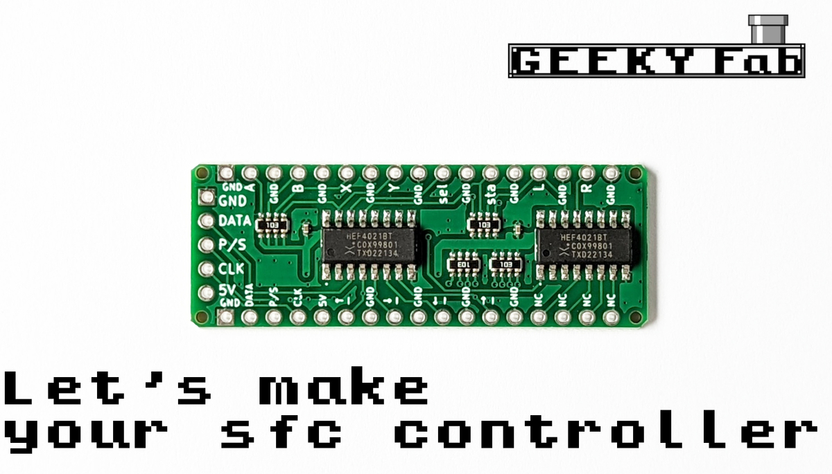
This is a very small SNES/SFC controller board.
By connecting each button terminal to the GND terminal through a switch or similar, you can easily build your own SFC controller.
Solder pin headers onto the terminals and you can also plug it into a breadboard.
Here are some of the ways you can use it:
- Building your own SFC controller or arcade stick
- Connecting an Arduino or Raspberry Pi to control the Super Famicom
- A great way to get started with DIY electronics
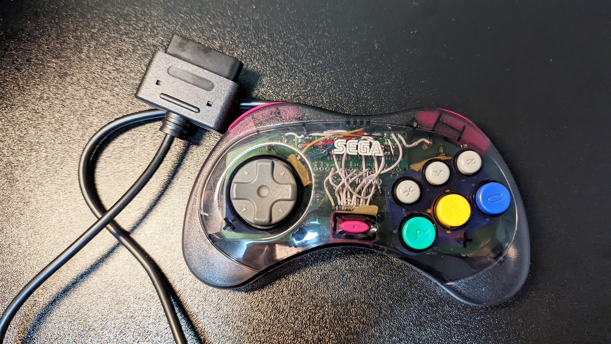
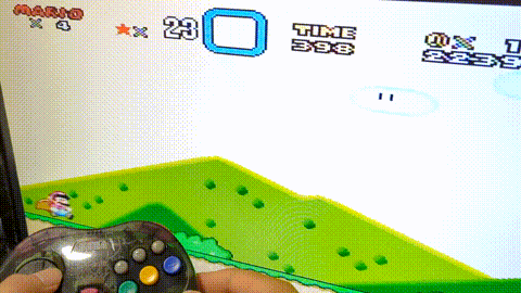
Product photos
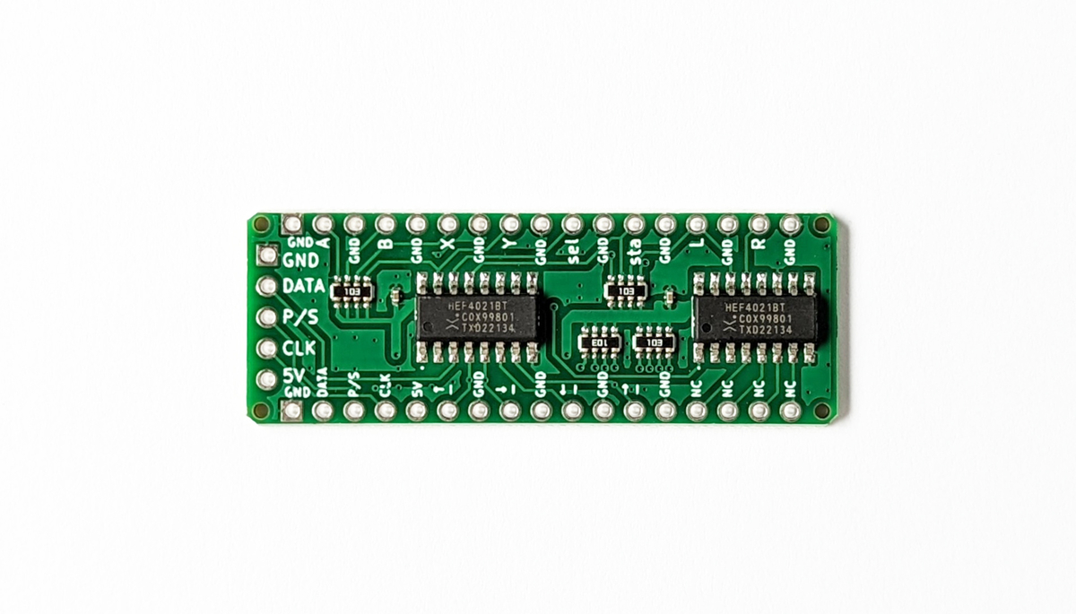
Specifications
Size: approx. 2cm x 5cm
Form factor: same shape as the Arduino Micro
Pin spacing: 2.54mm pitch
Compatibility
This PCB is compatible with the original Super Nintendo Entertainment System (SNES) and Super Famicom controller interface.
Connect a SNES/SFC controller cable to the board’s GND, DATA, LATCH, CLOCK, and 5V pins, then wire each button input to GND through a switch.
Important note
Wire colors may vary depending on the cable. Always verify each wire with a multimeter before soldering.
This product is for the original SNES/Super Famicom controller port and is not directly compatible with the Super NES Classic Edition / SNES Mini controller port.
How to assemble
Just solder the connections as shown in the wiring diagram below.
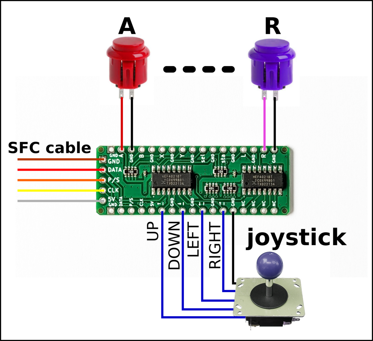
The idea is to connect a button between each button terminal and the GND terminal.
The five terminals on the left are for connecting the SFC cable.
How to attach the cable
You can prepare a cable in one of the following ways, for example:
- Repurpose the cable from an original SFC controller
- Buy one from AliExpress (the ones linked below worked for me.)
- Make one by cutting a commercial extension cable
- Amazon: SFC controller extension cable (untested)
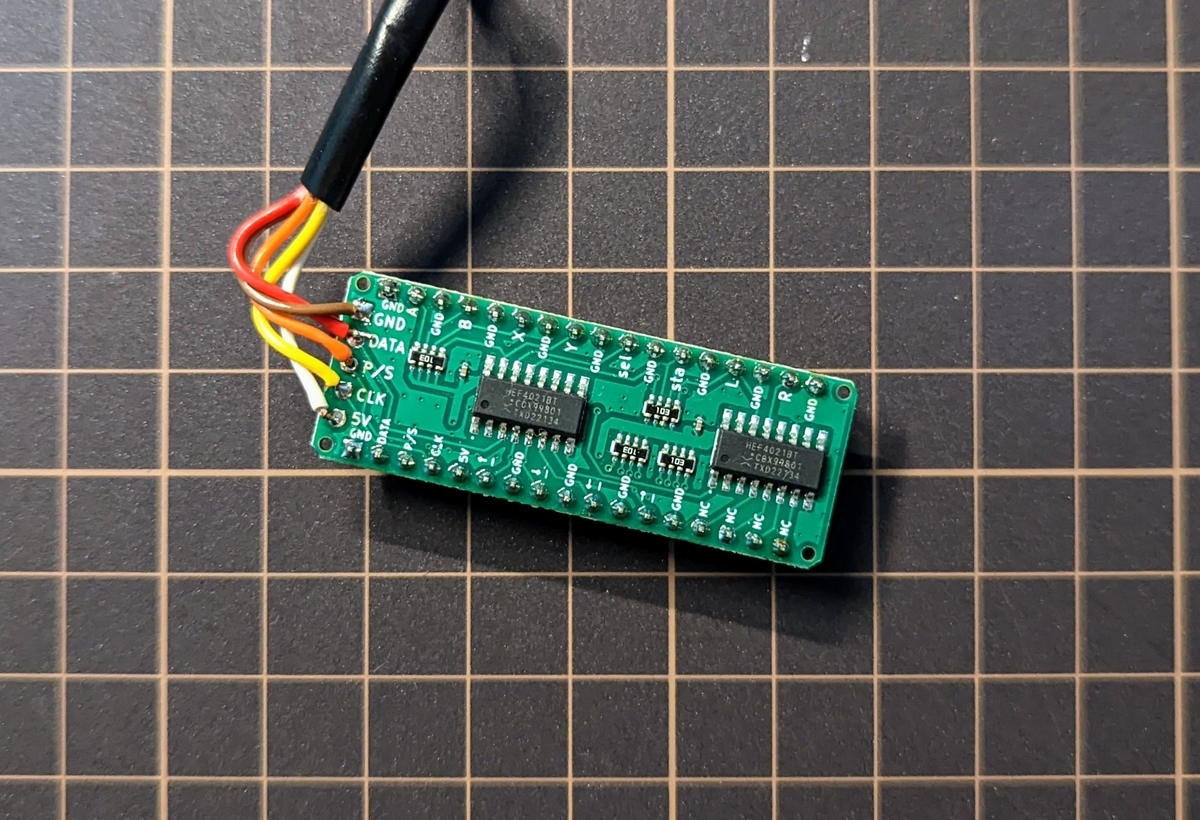
If you’re repurposing the cable from an original SFC controller, cut the cable, strip the insulation, and solder the wires starting from pin 1 (the GND pin) of the board in this order: brown, red, orange, yellow, white.
The pin order on this product matches that of the original SFC controller, so I think you can do it easily without much guesswork.
If you’re using a cable bought from AliExpress, or a commercial extension cable that you’ve cut, you’ll need to figure out which colored wire carries which signal.
The SFC-side pinout is shown in the figure below, so use a multimeter or similar to check which colored wire connects to each pin.
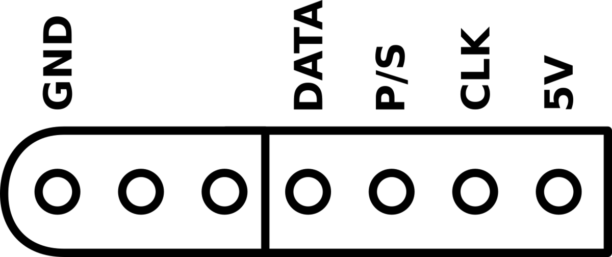
For reference, the cable I bought on AliExpress was: brown = GND, red = DATA, yellow = P/S, blue = CLK, green = 5V.
About pin headers
If you want to play around with it on a breadboard, it’s a good idea to add pin headers.
Pin headers with a 2.54mm pitch will work.
Build diary

Product inquiries
Feel free to reach out at this email address.
support@geekyfab.com