
Editor’s note: This is an English translation of an article originally published in Japanese in August 2023 (read the original — Japanese article). For the latest information on the product covered here, see its product page. Some details — distribution status and the games shown — reflect that time.
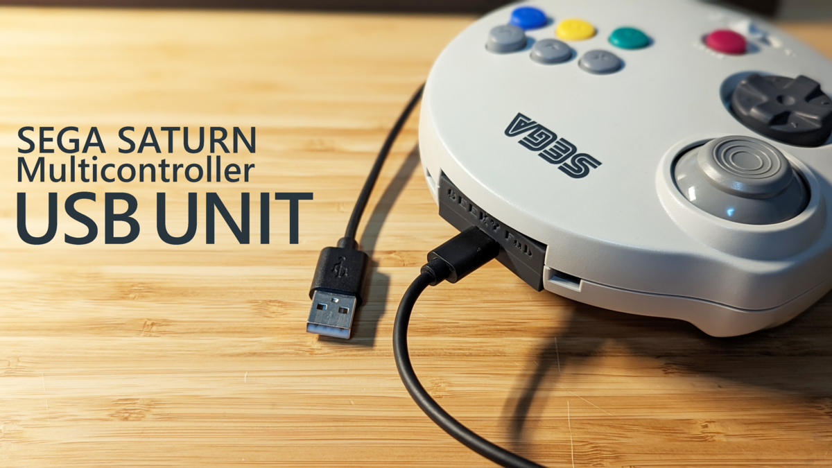
I built an extension unit that turns the SEGA Saturn 3D Control Pad — known in Japan as the Sega “Multi Controller,” or “Marucon” — into a USB device.
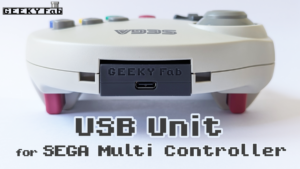
Swap it in for the Saturn 3D Control Pad’s standard unit, and the pad turns into a USB gamepad. Pretty slick, right?
More than 20 years after SEGA said an “extension unit is coming soon,” it has finally become a reality.
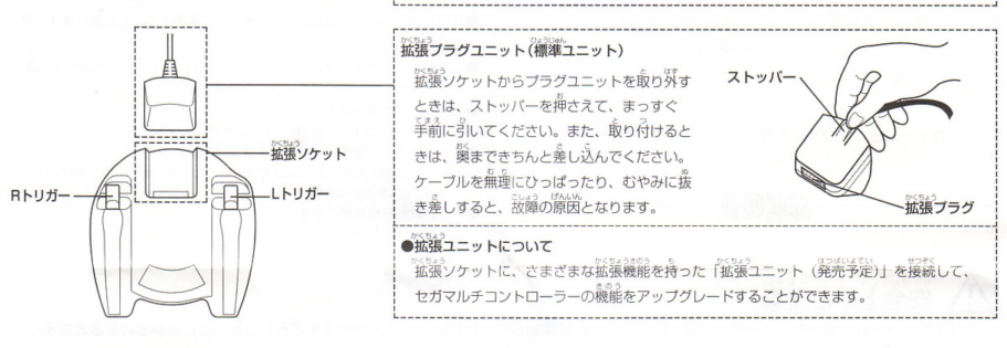
Source: https://segaretro.org/images/9/9e/MultiControllerSaturnJPManual.pdf
What I Made
I put together a short demo video.
I’ve put together the details — where to get it, its features, and so on — on a separate page.
Why I Made It
Do you have an old game console you used to play but don’t anymore?
Maybe it’s shoved in the back of a closet, or sitting on a shelf gathering dust — feels like a waste, doesn’t it?
It still works, but it never gets used. You almost feel sorry for it, even a little guilty. You know that feeling, right?
So I decided to build something like this, to give them a chance to be played again.
On top of that, the Saturn 3D Control Pad’s analog stick is a contactless type that uses Hall sensors, so there’s no wear-related degradation — it still works perfectly well today.
And it doesn’t suffer from the kind of drift you get on the Switch.
It’d honestly be a waste not to play with it again.
So, let’s build it.
The Spec I’m Going For
First, I thought about what approach to take for turning the pad into a USB device.
The first idea I had was to swap out the entire board inside the controller.
I’d already used this approach to convert the Saturn Control Pad and others to USB, so there was precedent.
But once I took it apart, swapping the whole board looked tough.
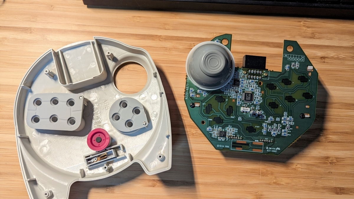

The stick and LR triggers use Hall sensors
The use of Hall sensors is a distinctive feature.
Since there’s no physical contact, the stick and LR triggers wear out less, making for a design that’s less prone to drift and failures.
It looked pretty difficult, so I shelved the whole-board-swap approach for now and started thinking about other options.
The next idea was to swap out the board in the standard unit.
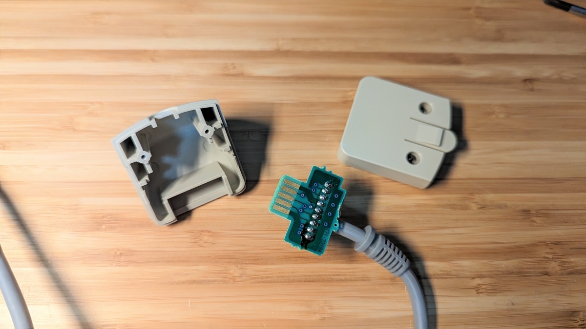
The method is to put a board that converts the pad’s signals to USB inside the unit, turning it into a USB device.
My concerns here were whether I could build the conversion circuit and write the program, and whether the conversion board would actually fit inside that tiny unit.
I wouldn’t know without trying, so I decided to go ahead and build it this way for now.
Researching the Pad’s Signal Spec
Whether I’m drawing a circuit or writing a program, nothing gets started until I understand the signal spec.
Luckily, the Sega Saturn is old hardware by now, so if you search online you’ll find the specs scattered all over the place.
The controller’s pin assignments are here, for example.
Beyond that, I figured things out by probing the real hardware with a multimeter and the like.
For the signal spec and other fine details, this site is incredibly helpful. What even is this page…
The Marucon’s spec is around p.97 of this document, I think.
Roughly speaking, when the host (the Sega Saturn console) toggles TH and TR back and forth, the controller returns the state of each button in sequence, and the host reads them off.
So, let’s start drawing the circuit based on this kind of information.
Hardware
Drawing the Schematic
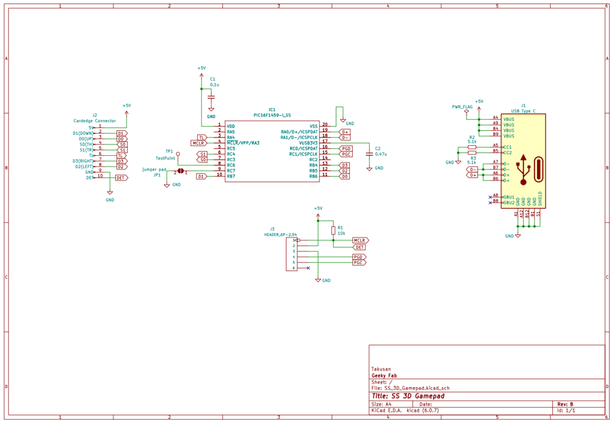
Let me just show you the whole thing right away — here it is.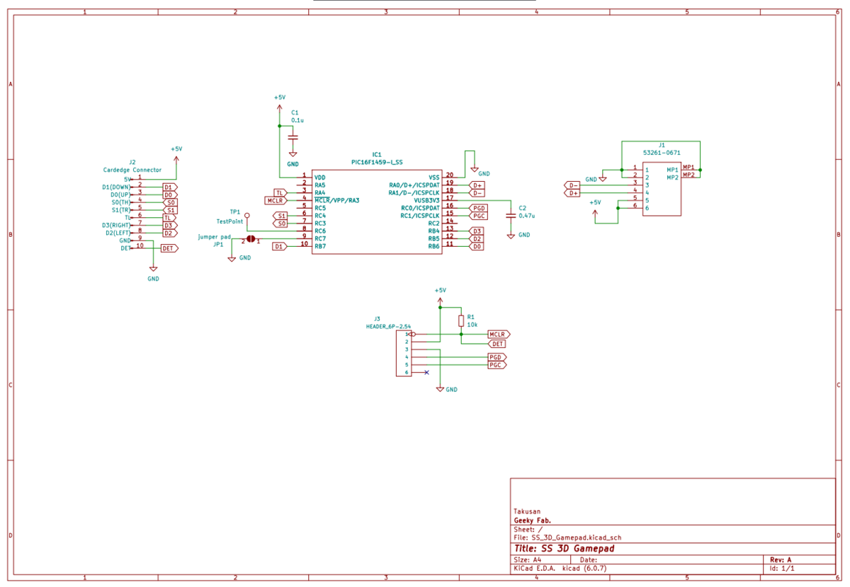
Basically, the pad’s input goes straight into a PIC microcontroller, and I designed it with as few parts as possible.
It needs to be compact, after all.
One key point is using pin 10 of connector J2 on the pad side as the DET terminal.
On the pad side it’s a pin tied to GND, and the plan is to connect it to the microcontroller so I can monitor whether the pad is plugged in.
Laying Out the Board
I laid out the board to fit the unit’s shell.
And here’s what I came up with.

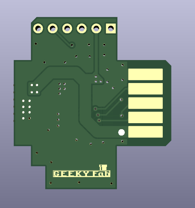
The key question was whether I could shrink it down enough to fit inside the unit, but I managed to place all the parts somehow.
Next up: manufacturing.
Manufacturing the Board
I send the board’s Gerber data off to a manufacturer to have the boards made.
This time I went with JLCPCB.
The order option to watch out for is the surface finish.
Since this is a card edge, gold plating would really be the right choice, but as this is a prototype I ordered it with HASL (solder leveling) for now.
Soldering the Components
Since this is a trial run, I hand-soldered the parts one by one.
Like this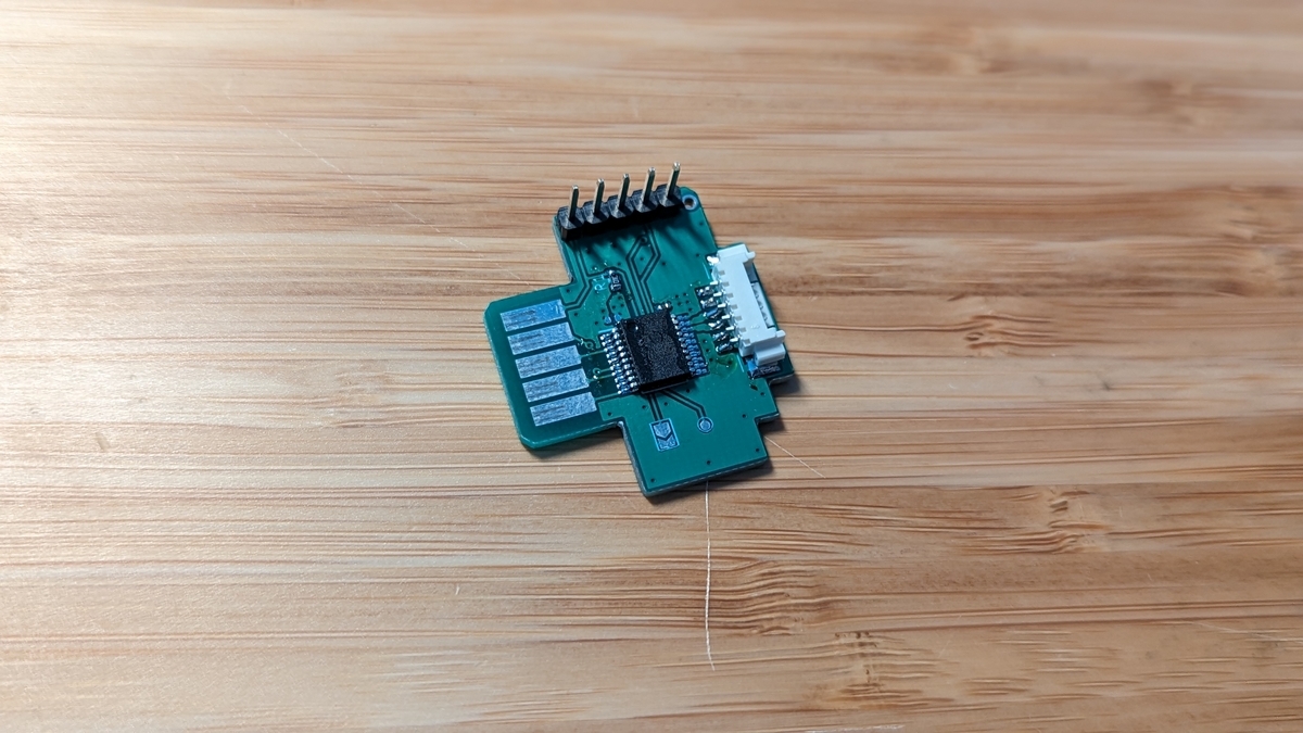
With the cable attached, it looks like this.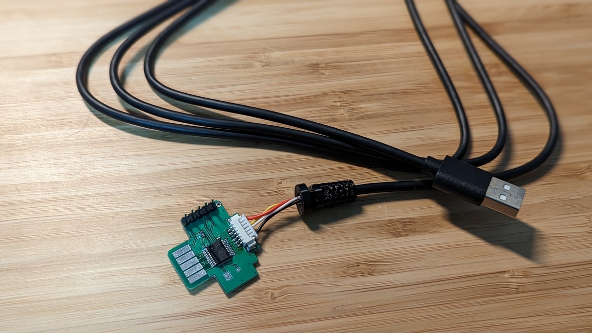
And it fits the unit perfectly.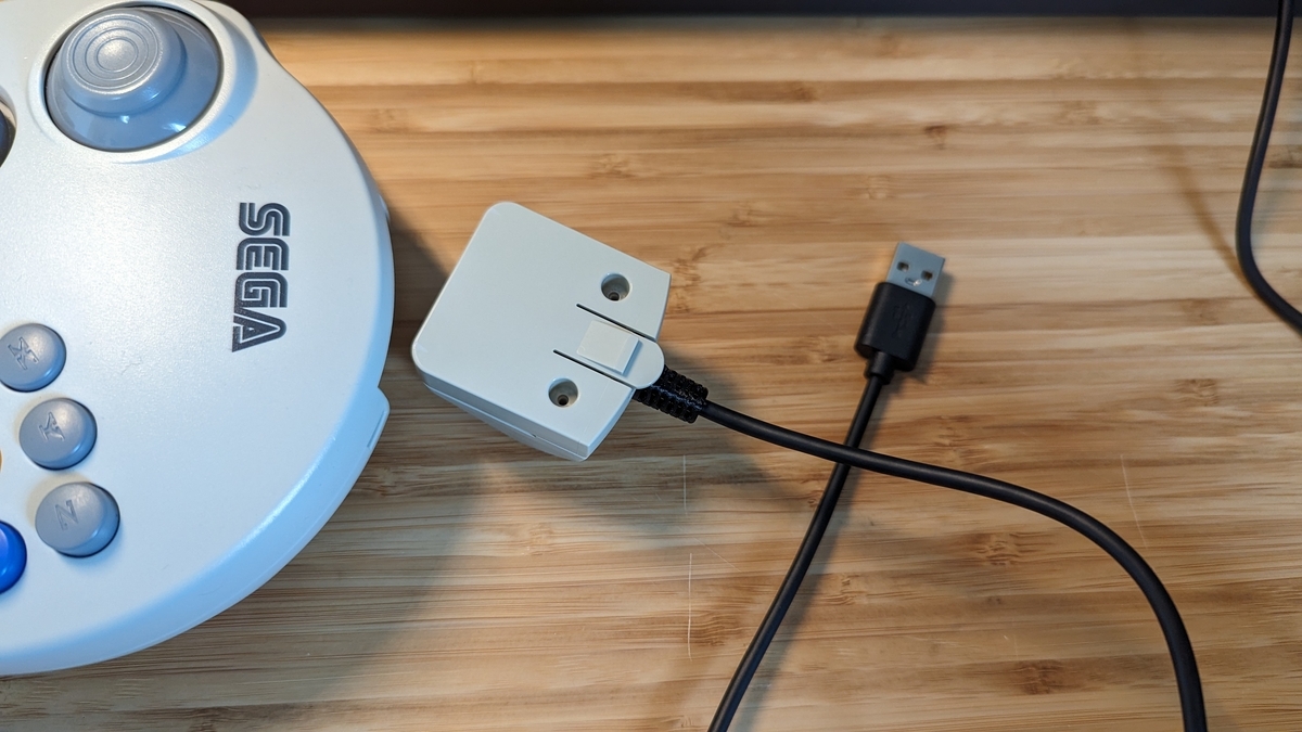
Deciding to Make the Shell Too
It came out nicely, so I was about to move forward with it — and then it hit me.
“Wait, couldn’t I make the extension unit’s shell too, with a 3D printer?”
So I went ahead and designed the extension unit’s shell as well.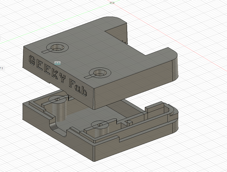
It took a fair bit of trial and error with the 3D printer, but I think it turned out pretty well.
You can get surprisingly far with this stuff.
The final production needed precision, so I made it with the resin (SLA) type of JLCPCB’s 3D printing service.
I tried a few options, and the black resin looked the best.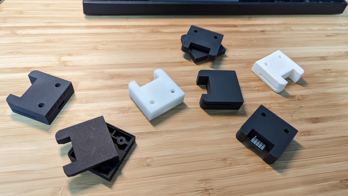
Redesigning the Circuit and Board
I redesigned the circuit and board to match the new shell.
I switched the connector to USB Type-C and adjusted the board outline.
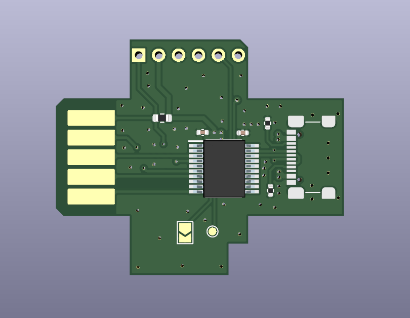
Board layout rev.B
Putting the Shell and Board Together
Here’s how it looks with the new board and shell combined.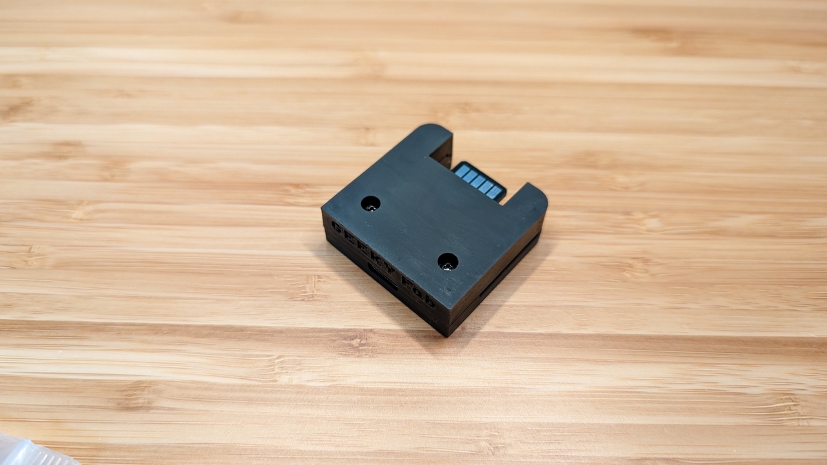
And it fits the pad perfectly.
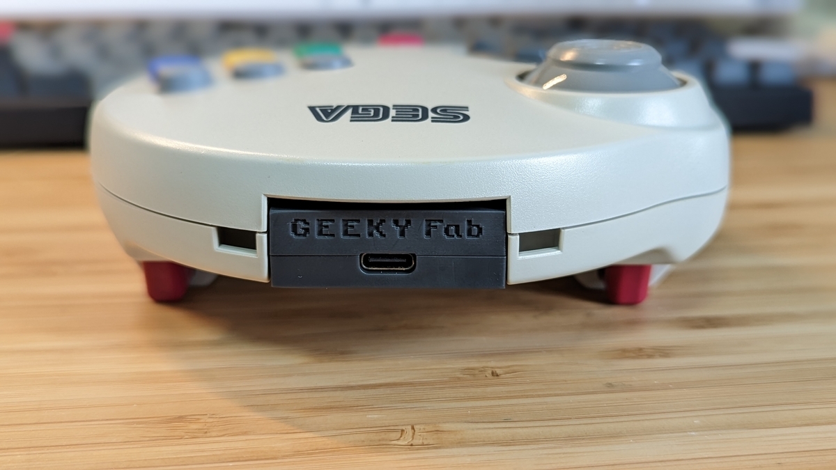
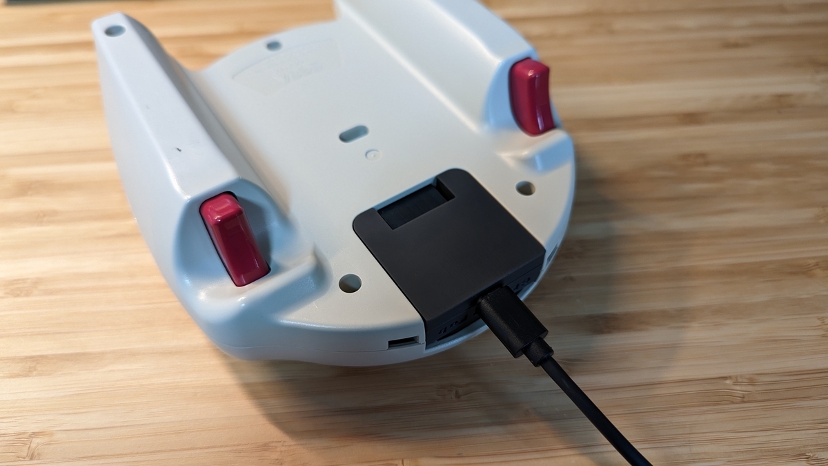
Here’s what it looks like with USB Type-C plugged in.
That wraps up the hardware design.
Nice.
Software
Writing the Program
The question is how to receive the signals coming from the pad and convert them to USB.
That said, as mentioned earlier the spec is written up here, so really it’s just a matter of implementing it.
I’ve published the source code on GitHub, so please take a look there for reference.
I also included a USB bootloader again this time.
With this in place, you can rewrite the firmware over USB, which is handy.
On startup it checks whether the adapter is connected to the pad, and if it isn’t, the bootloader launches — something along those lines.
Oh, and I also made an Xinput-mode version as an additional firmware.
Trying It Out
I flashed the program onto the finished adapter and gave it a try.
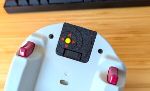
The behavior changes properly when you switch between analog and digital mode — looking good.
I tried playing a variety of games, just as in the demo video at the top.
It looks chunky, but it fits the hand really well.
Wrapping Up
This time I built an extension unit that turns the SEGA Saturn 3D Control Pad into a USB device.
It’s a controller from more than 20 years ago, yet the analog stick still responded with great sensitivity.
Because the analog stick and LR triggers are contactless, it has a feel you can’t get from any other controller — really nice.
I’ll be releasing it for sale soon, so stay tuned.It’s now on sale on Tindie and BOOTH. (Tindie ships worldwide, so you can order it from outside Japan.)
GEEKY Fab. BOOTH Store
That’s it for this time.
Thanks for reading.
Comments