
Editor’s note: This is an English translation of an article originally published in Japanese in January 2022 (read the original — Japanese article). For the latest information on the product covered here, see its product page. Some details — the shops, software versions, and games shown — reflect that time.
This time I made a board that turns a Super Famicom (SFC) controller — the SNES outside Japan — into a USB gamepad.
In this article, I’ll walk through the build process of the USB-gamepad conversion board for the SFC controller, step by step.
I’ve published the design data on github, so please give building your own a try too.
A Quick Note
The board featured in this article has been turned into a product, and it’s sold at the shops below.
If you’re interested, please take a look.
Now, on to the main story.
Here’s the Spec I’m Aiming For
I’m making a USB gamepad board that fits perfectly inside the SFC controller’s housing.
The SFC controller doesn’t have many buttons, so to make it work with modern games too, I’ll let you change the button assignment by holding the Start or Select button.
Drawing the Schematic
Here’s what the overall schematic looks like.
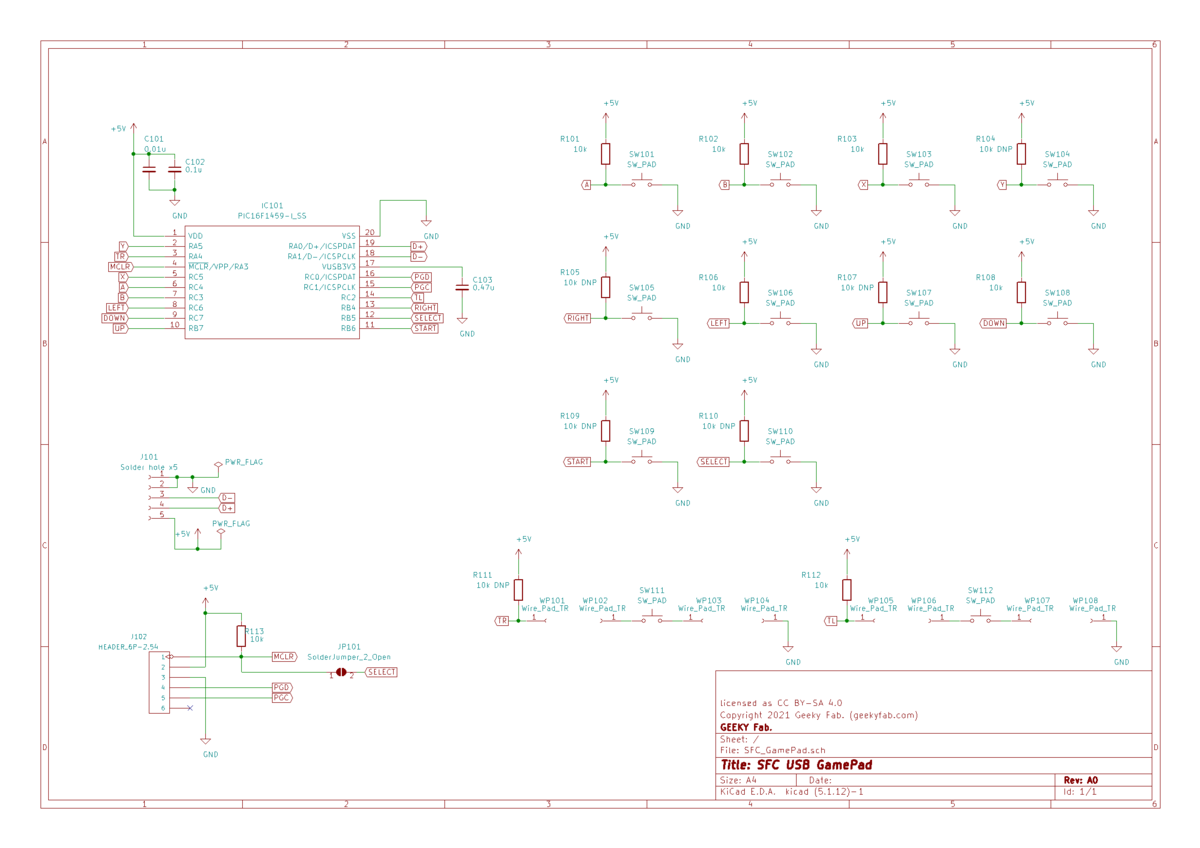
Basically, the circuit connects the button pads directly to the I/O ports of the PIC16F1459, which is the main microcontroller.
On the PIC16F1459, some I/O ports seem to have an internal pull-up resistor and some don’t, so just in case I added a land for a pull-up resistor on every button pad.
The Main Microcontroller: PIC16F1459
For the main microcontroller, I’m using the PIC microcontroller PIC16F1459.
This PIC is what’s commonly called a USB microcontroller — it can act as a USB device.
Another nice thing is that it has a lot of I/O ports.
It can cover all of the SFC controller’s buttons without building a key matrix or similar circuitry, which keeps the circuit simple.
Drawing the PCB Artwork
This is the heart of the project.
I measured the actual dimensions of the SFC controller’s housing and board, and designed the artwork so it fits snugly into the housing with the button positions lined up.
That said, getting a board to fit the SFC housing perfectly on the first try is hard, so I went through a cycle of manufacturing a board, fine-tuning it, making it again, and so on.
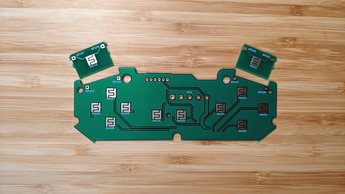
And here’s the artwork I ended up with.
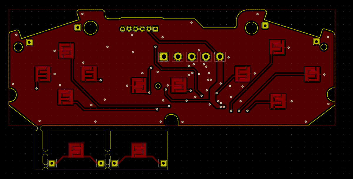
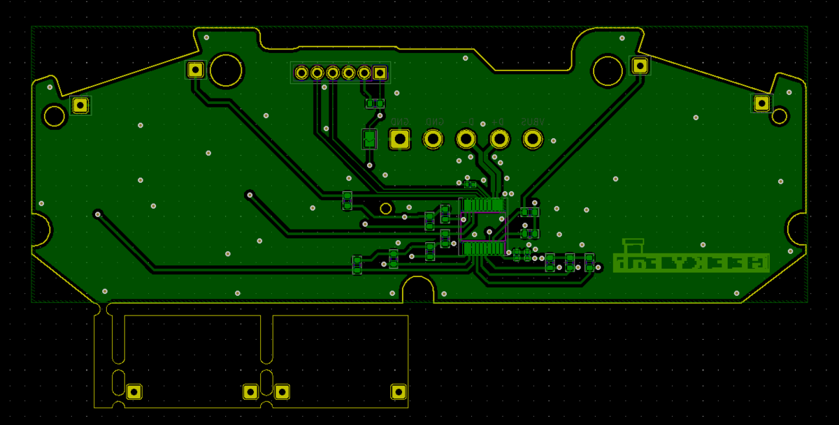
USB gamepad conversion board for the SFC controller — back
The little piece sticking out at the bottom-left is the board for the L and R buttons.
Getting the Boards Made
I ordered the board manufacturing from Allpcb.
I mostly went with the default options, but for the surface finish you need to select gold plating.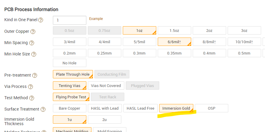
This is to keep the button pads from oxidizing.
With a solder-leveler finish or bare exposed copper, the button pads would oxidize and stop responding, so gold plating prevents that oxidation.
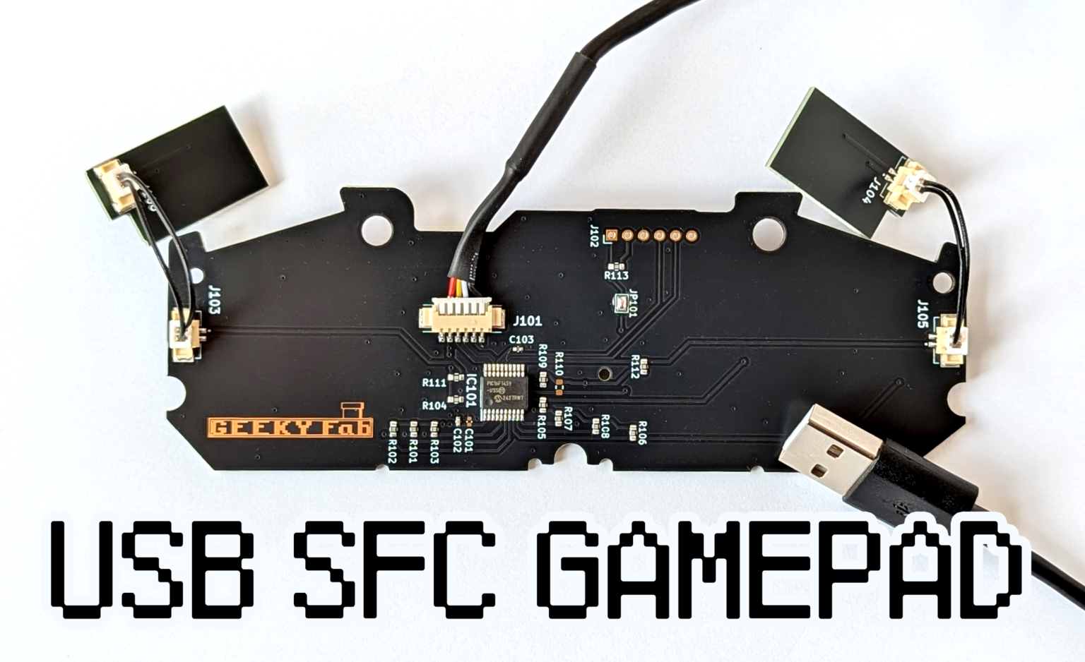
And here are the boards that arrived.
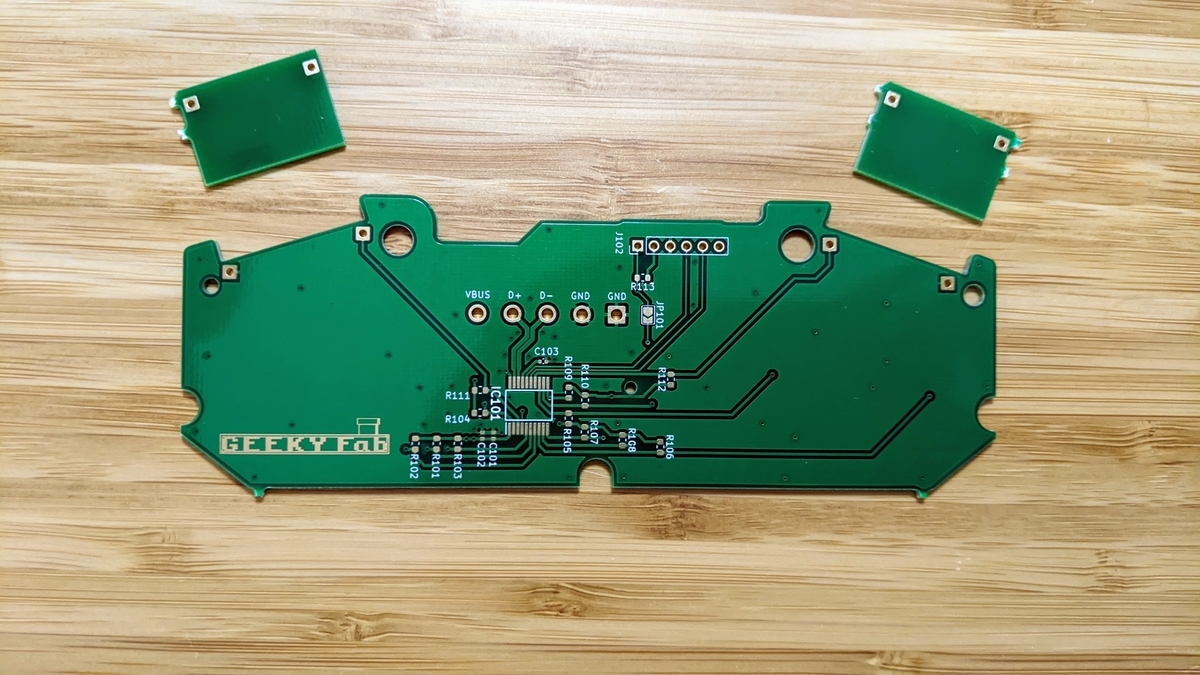
The SFC controller USB gamepad board as delivered — back
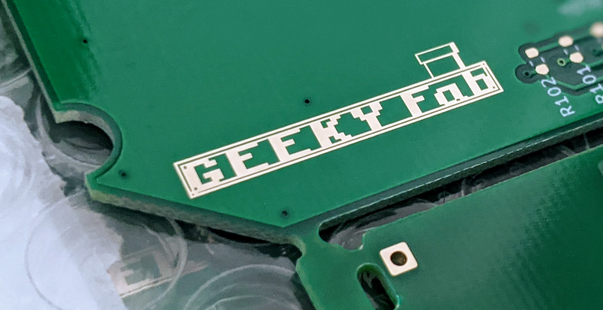
The gold plating makes for a shiny, good-looking board.
I made the logo by leaving the solder resist open so the plating shows through, and it turned out pretty cool.
Mounting the Components
Let’s get the components mounted right away.
And here’s the board after assembly.
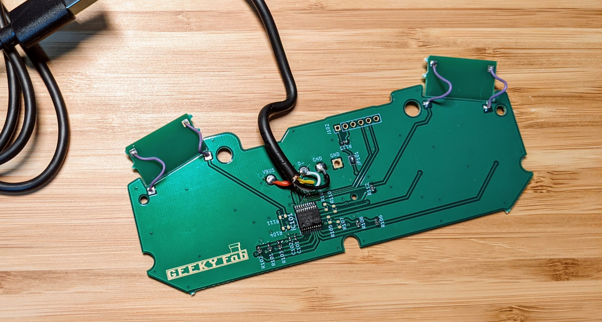
If I were distributing these I’d build them more neatly, but this one’s just for me, so this is good enough.
Writing the Program
The full source code for the USB gamepad board is published on GitHub, so in this article I’ll just cover a few key points.
This program is built on top of the Microchip Libraries for Applications (MLA) provided by Microchip.
The MLA includes sample project files for each PIC microcontroller.
For example, the USB Joystick sample project for the PIC16F1459 I’m using should be in the following path:
mla\v2018_11_26\apps\usb\device\hid_joystick\firmware\low_pin_count_usb_development_kit_pic16f1459.x
Configuring the PIC’s Ports and Initializing the Timer
The PIC’s port configuration and timer initialization are done near the start of main() in main.c.
    /* set all ports input*/
TRISA = 0x30;
TRISB = 0xf0;
TRISC = 0xff;
/* enabling internal pull up*/
OPTION_REGbits.nWPUEN = 0;
WPUA = 0x30;
WPUB = 0xf0;
/* all ports used as degital ports.*/
ANSELA = 0x00;
ANSELB = 0x00;
ANSELC = 0x00;
/* initializing timer0 and interruption*/
OPTION_REGbits.PS = 0b111;        // clock divided by 256
OPTION_REGbits.PSA = 0;         // enabling prescaler
OPTION_REGbits.TMR0SE = 0;      // edge select (rise)
OPTION_REGbits.TMR0CS = 0;      // clock source select (internal)
OPTION_REGbits.INTEDG = 1;      // interrupt edge select (rise)
//    INTCONbits.TMR0IF = 0;          // reset timer0 interrupt flag
//    INTCONbits.TMR0IE = 1;          // enabling peripheral interrupts
INTCONbits.GIE = 1;             // enabling interrupts
// setting initial value of timer 0.
// 1 clock = 256/16MHz = 16us
// the timer interrupt happens every 16us x 0xff(255) = 4080us .
//
// set the timer0 value so that timer interruption happens every 4000us.
// 80us / 16us = 5 clocks
TMR0bits.TMR0 = (uint8_t)5;
It’s all just as the comments say.
I set all the I/O ports as inputs, enable the internal pull-ups on every port that has one, and since the ports default to analog, I switch them all to digital.
Next, I set the parameters for Timer0.
The Data Type Used for USB Communication
The data type for the packet sent over USB is declared in app_device_joystick.h like this:
typedef union _INTPUT_CONTROLS_TYPEDEF
{
struct
{
struct
{
uint8_t y:1;
uint8_t b:1;
uint8_t a:1;
uint8_t x:1;
uint8_t L1:1;
uint8_t R1:1;
uint8_t L2:1;
uint8_t R2:1;//
uint8_t select:1;
uint8_t start:1;
uint8_t left_stick:1;
uint8_t right_stick:1;
uint8_t home:1;
uint8_t :3;    //filler
} buttons;
struct
{
uint8_t hat_switch:4;
uint8_t :4;//filler
} hat_switch;
struct
{
uint8_t X;
uint8_t Y;
uint8_t Z;
uint8_t Rz;
} analog_stick;
} members;
uint8_t val[7];
} INPUT_CONTROLS;
By storing values in these variables according to which buttons are pressed, you can drive the USB gamepad.
For example, when the “Y” button is pressed, I set the variable y to 1 and send it to the PC over USB.
That’s how the PC knows the “Y” button was pressed on the USB gamepad.
The Button-Handling Code
The button-handling code is written in my_app_device_gamepad.c.
This code handles:
- Monitoring the button states
- Handling Start/Select long-presses and managing the state
—that’s what this section does.
For monitoring button states, I just prepare a bit of simple code like the following for each button.
gamepad_input->members.buttons.select = BUTTON_IsPressed(BUTTON_SELECT);
For handling the Start/Select long-press, I use Timer0, which I initialized earlier on the PIC.
Below is the function for handling the Start long-press.
void ChangeSWMode_Button_Start(void){
uint16_t cnt_timer =0;
if (BUTTON_IsPressed(BUTTON_START)){
INTCONbits.TMR0IF = 0;          // reset timer0 interrupt flag
TMR0bits.TMR0 = (uint8_t)5;
cnt_timer = 0;
while(BUTTON_IsPressed(BUTTON_START)){
if(INTCONbits.TMR0IF){          // INTCONbits.TMR0IF happens every 4ms
cnt_timer++;
if(cnt_timer >=500){        // 2s
flags.sw_flag = ~(flags.sw_flag);
cnt_timer =0;
while(BUTTON_IsPressed(BUTTON_START));
}
INTCONbits.TMR0IF = 0;
TMR0bits.TMR0 = (uint8_t)5;
}
}
}
return;
}
USB HID report descriptors
There isn’t much material on USB HID report descriptors beyond the official documentation, and the spec itself is hard to follow, so this was quite a pain.
The relevant part is the following section in usb_descriptors.c.
const struct{uint8_t report[HID_RPT01_SIZE];}hid_rpt01={{
0x05,0x01,        //USAGE_PAGE (Generic Desktop)
0x09,0x05,        //USAGE (Game Pad)
0xA1,0x01,        //COLLECTION (Application)
0x15,0x00,        //  LOGICAL_MINIMUM(0)
0x25,0x01,        //  LOGICAL_MAXIMUM(1)
0x35,0x00,        //  PHYSICAL_MINIMUM(0)
0x45,0x01,        //  PHYSICAL_MAXIMUM(1)
0x75,0x01,        //  REPORT_SIZE(1)
0x95,0x0D,        //  REPORT_COUNT(13)
0x05,0x09,        //  USAGE_PAGE(Button)
0x19,0x01,        //  USAGE_MINIMUM(Button 1)
0x29,0x0D,        //  USAGE_MAXIMUM(Button 13)
0x81,0x02,        //  INPUT(Data,Var,Abs)
0x95,0x03,        //  REPORT_COUNT(3)
0x81,0x01,        //  INPUT(Cnst,Ary,Abs)
0x05,0x01,        //  USAGE_PAGE(Generic Desktop)
0x25,0x07,        //  LOGICAL_MAXIMUM(7)
0x46,0x3B,0x01,   //  PHYSICAL_MAXIMUM(315)
0x75,0x04,        //  REPORT_SIZE(4)
0x95,0x01,        //  REPORT_COUNT(1)
0x65,0x14,        //  UNIT(Eng Rot:Angular Pos)
0x09,0x39,        //  USAGE(Hat Switch)
0x81,0x42,        //  INPUT(Data,Var,Abs,Null)
0x65,0x00,        //  UNIT(None)
0x95,0x01,        //  REPORT_COUNT(1)
0x81,0x01,        //  INPUT(Cnst,Ary,Abs)
0x26,0xFF,0x00,   //  LOGICAL_MAXIMUM(255)
0x46,0xFF,0x00,   //  PHYSICAL_MAXIMUM(255)
0x09,0x30,        //  USAGE(X)
0x09,0x31,        //  USAGE(Y)
0x09,0x32,        //  USAGE(Z)
0x09,0x35,        //  USAGE(Rz)
0x75,0x08,        //  REPORT_SIZE(8)
0x95,0x04,        //  REPORT_COUNT(4)
0x81,0x02,        //  INPUT(Data,Var,Abs)
0xC0              //END_COLLECTION
}
};
If there’s interest, I’d like to cover how to write this in a separate article.
About the Program’s License
Most of the MLA source code provided by Microchip is licensed under Apache License 2.0.
I’ve decided to release the source code I added under Apache License 2.0 as well, so feel free to use it however you like, whether for personal or commercial use.
However, the USB Product ID (PID) is provided under a sublicense agreement with Microchip, so it cannot be used commercially.
As a file, my_usb_pid.h is the one that’s off-limits for commercial use.
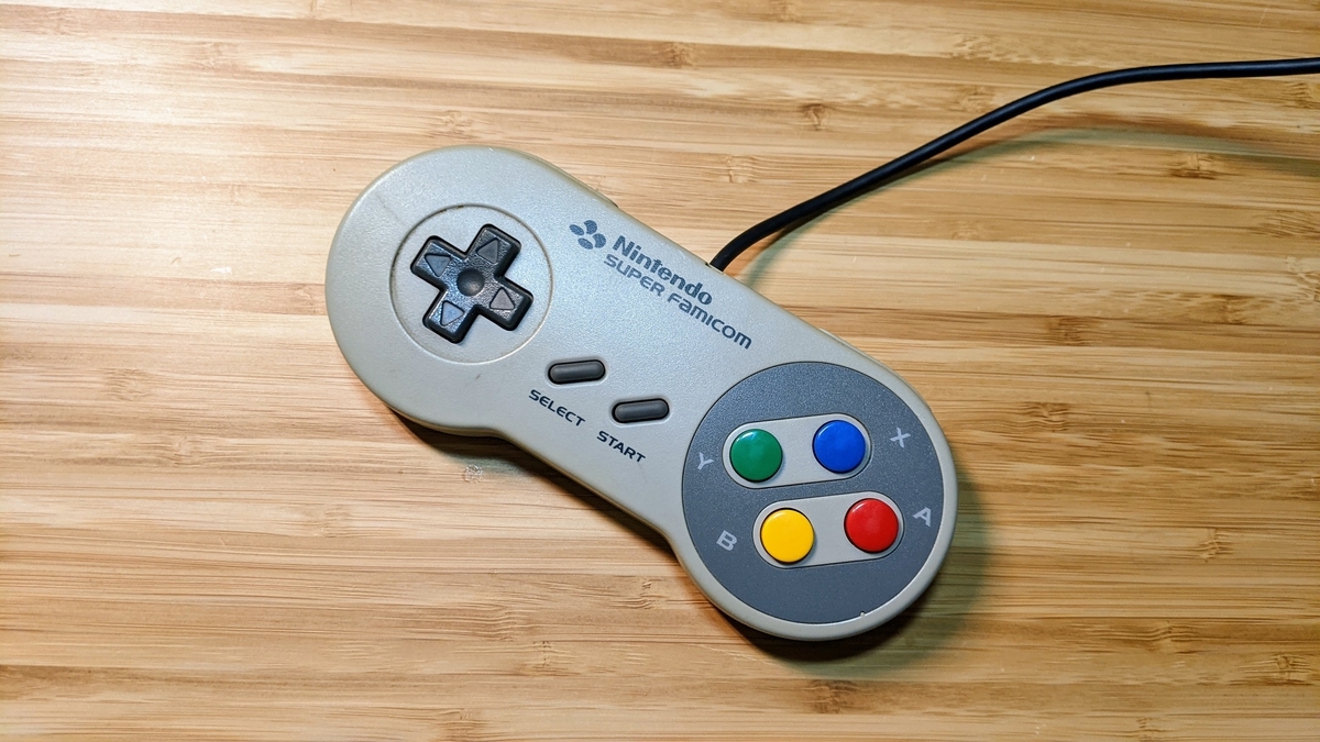
Modifying the SFC Controller
Once you flash the finished program onto the board with a PICkit 3, the board is complete.
So let’s go ahead and use the finished board to turn an SFC controller into a USB gamepad.
Take this,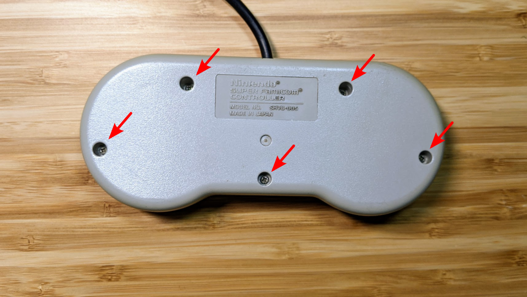
do this,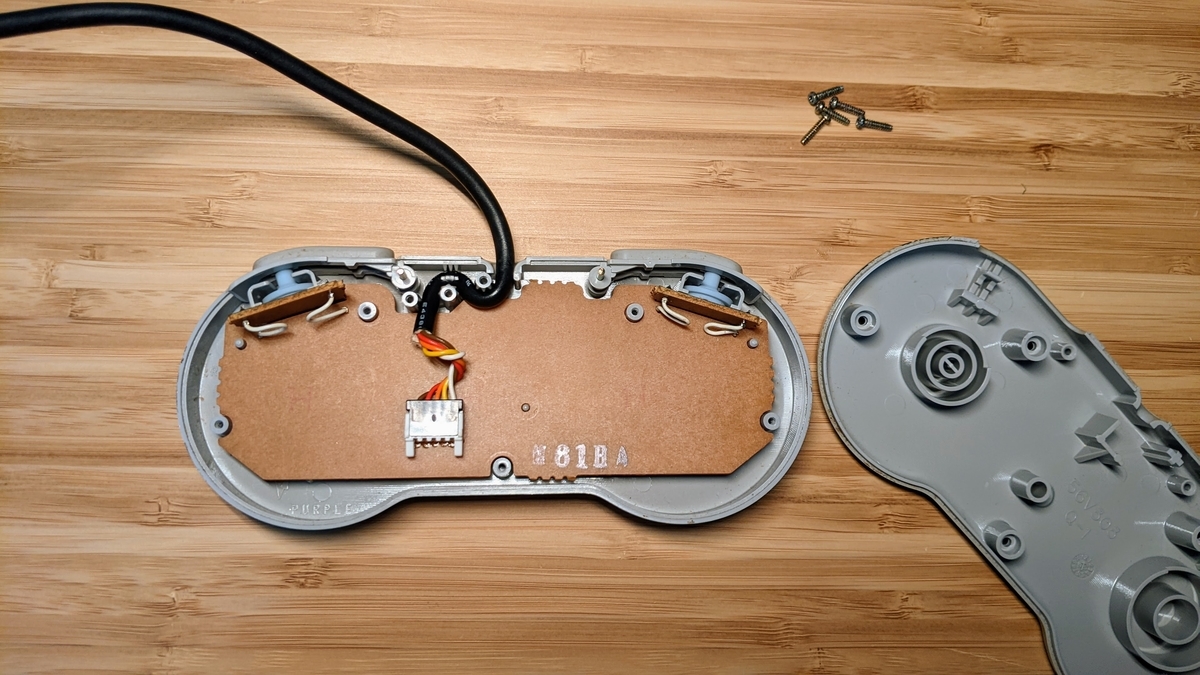
then this,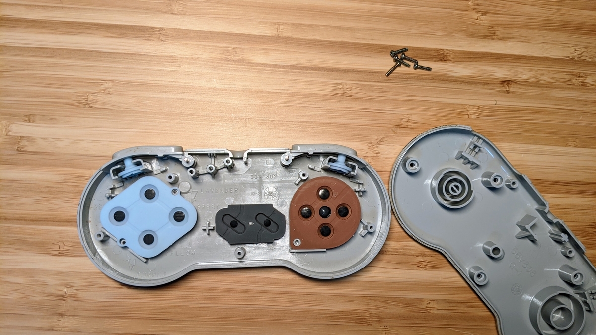
and… there we go.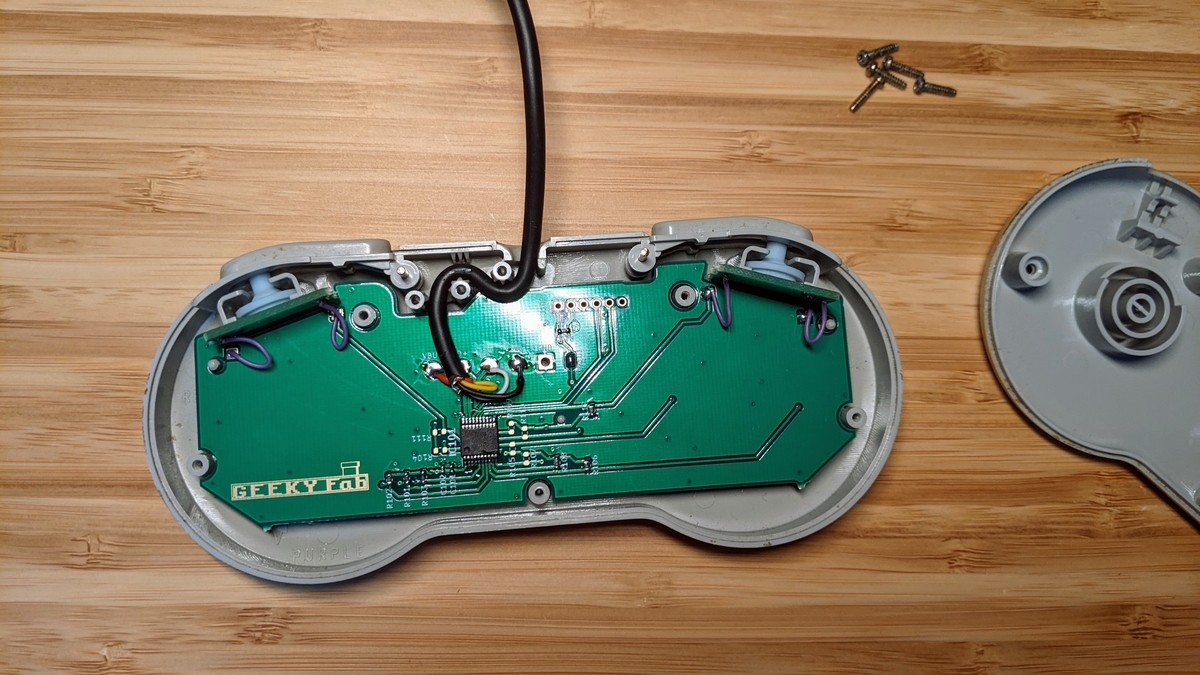
Put the cover back on, and it’s done.
Let’s fire it up.
Trying It Out
Testing on Windows
First, let’s check that it works.
When I plugged it into the PC, “SFC Gamepad” showed up properly in the Control Panel, recognized.
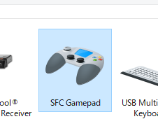
Now, right-click the icon above → “Game controller settings” → “Properties” to bring up the gamepad test screen.
And here’s what it looks like when you move it.
Function check (testing the Start long-press feature)
It’s working solidly.
I was pretty happy when it ran for the first time.
Testing on Raspberry Pi
I also tested it on a Raspberry Pi.
To use a gamepad on the Raspberry Pi, you use the “joystick” package.
And for testing, “jstest-gtk” is easy to work with.
First, run the following command from the terminal to install these packages.
sudo apt install joystick jstest-gtk
Next, run the following command from the terminal to launch jstest-gtk.
jstest-gtk
From there, it’s the same as on Windows.
Here are the OSes I ended up testing on:
- Raspberry PI 3
- Raspberry Pi OS
- Recalbox for RASPBERRY PI 3
- RetroPie 4.7.1 for RASPBERRY PI 2/3
- Raspberry PI 4
- Raspberry Pi OS
- Recalbox for RASPBERRY PI 4/400
- RetroPie 4.7.1 for RASPBERRY PI 4/400
I haven’t checked others, but since it doesn’t use any special drivers and runs on the standard driver, it’ll probably work on them too.
Playing Games on Steam
I tried playing some Steam games with the USB-gamepad-converted SFC controller.
First up, a Bomberman battle-royale game I played a lot on the Super Famicom as a kid: “Super Bomberman R Online”.
Getting to play the latest Bomberman with an SFC controller — I’m honestly moved…
“DELTARUNE”, the new game from Toby Fox, the creator of one of my favorite games, “UNDERTALE”.
Even though it’s a recent game, playing it with an SFC controller feels completely natural.
The modern 3D party game “Fall Guys”.
I figured this one would be a stretch, but it played just fine!
“Cuphead”, with its 1930s-cartoon look.
It suits the SFC controller incredibly well.
Trying to Play on EPIC Games…?
EPIC Games seems to support only a limited set of controllers, so I couldn’t play…
I really wanted to play FORTNITE, too…
<Follow-up>
We’ve released Xinput-compatible firmware for this board, so you can flash it on and play Fortnite and other Epic Games titles. (Honestly, the SNES controller has too few buttons to really play Fortnite — but it does run.)
Grab the firmware from the product page.
Wrapping Up
This time, I built a board for converting a Super Famicom controller into a USB gamepad, actually modified an SFC controller with it, and played some games.
I really love the Super Famicom controller, and the urge to play modern games with it too is what kicked off this project.
In the end, I’m really happy with how it turned out.
The Gerber data for the board and the firmware source code are published on GitHub, so if you’d like, please give building one a try.
That’s it for this time.
With button remapping and Switch / XInput support, the controllers you grew up with work in all kinds of environments.
Comments